EMERSON Manual Bristol Flow Measurement Applications
Summary
This comprehensive guide details Orifice Plates and associated flowmeter systems, essential devices for accurately measuring gas and liquid flow rate using differential pressure principles. The manual provides detailed instructions on proper installation practices—including selecting optimal meter locations and ensuring flawless piping connections—as well as vital guidelines for maintenance and performance calibration. It is intended for engineers, technicians, and industrial facility managers who require dependable, precision measurement solutions from their primary fluid control equipment.
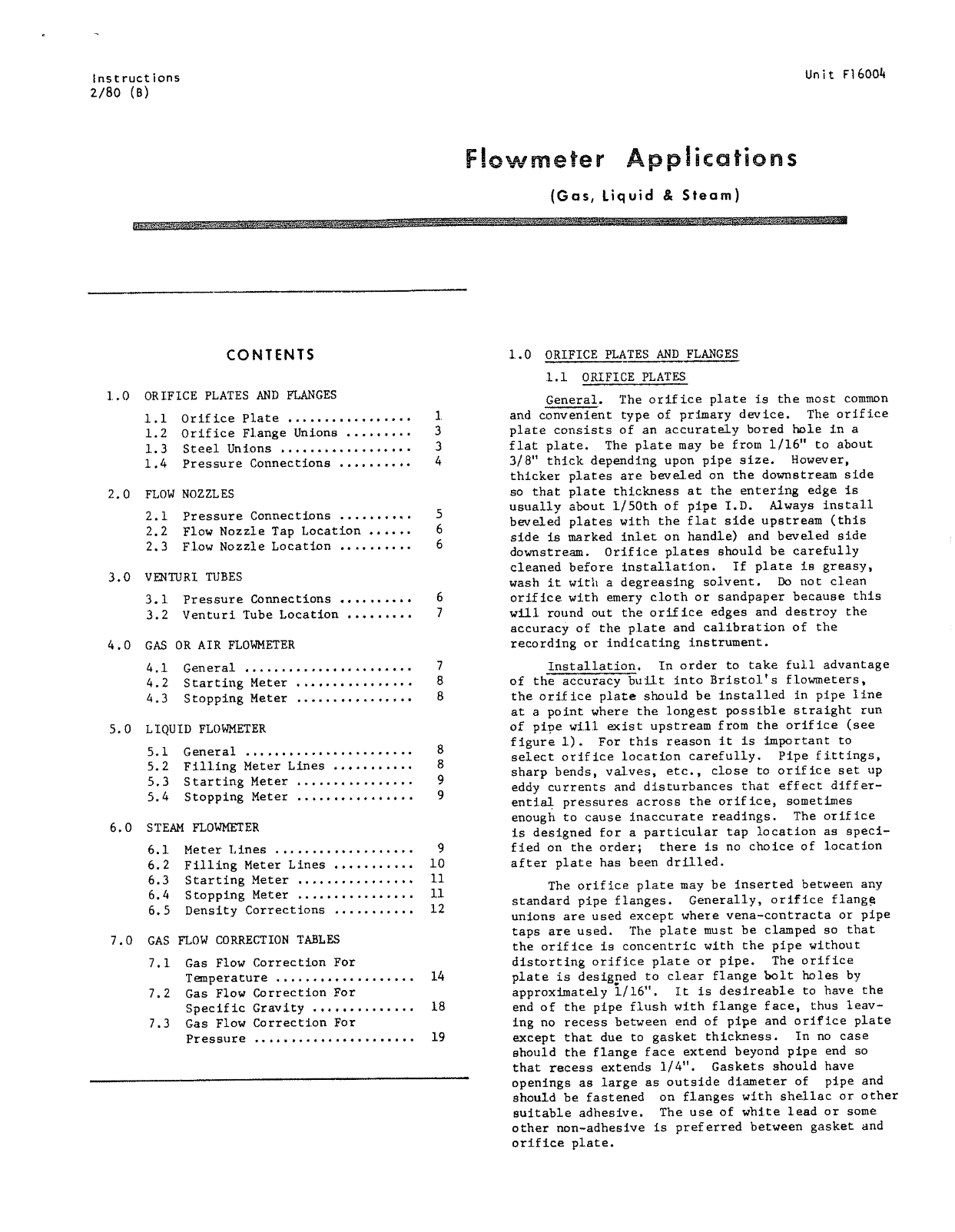
Page 1 Text Content
Unit F16004
(Gas, tiquid 良 Steaim)
CONTENTS 1.0 0RIFICE PLATES_ AND FLANGES
斌 1 DORIFICE PLATES
ORIEFICE PLATES AND FLANGES
General。 The cordtfice plate TI9 the ost Common
and convenient type of prtmary devjice. The ordlfice
.1 Ort EIice Plate ,eyeooo,
Plate consists of an accurate Ly bored ho Ie fn 了 a
.2 Orifice Flange Uniong ..。
flat plate, The Plate may be from 17/16"” to about
1.3 Steel Unions ,ee
人 wo 二 378"” thjck depending upbon pipe size。 However,
1.4 Pressure Donnect Jons .iv
thicker Plates are beveled on the downe Btream sjde 5 that plate thickness at the enter3ng edge 了 8
FLOW NO2ZZLES
usually about TI/50th of pipe I.D。 Away Ss dnstall
2.1 Pressure Connections .…
beveled plates with the flat side UPBtream 《thjs
2.2 Flow Nozzte Yap Locatlon
slde fs marked intet on handje) and beveled side
2.3 了 1ow Nozzle Location ……
downstream, Driftice PLates 6hotld be carefuliy cleaned before installation, If plate TB6 greasy,
VENTURI TUBES
Wash it with a degreaslng Sozivent, Do noc clean 3.1 Pressure Cornnections 。 ordffice with emery eloth or sandpaper becau8ge [hi Ss 3.2 Venturi TYube Location ,..,. wj Yound out the orifjice edges and destroy fthe
acecuracy of khe plate and calibration of the GAS 0OR AITR FLOWMETER recording of indicating instrument,。
TInstallation。 In order to take full advantage
1T Generst oo
of the ac Curacy bujiit into Brisctol's fl Lowmeters,
4.2 Starting Meter ,。, 本
the oriflee plate should be installed in Pipe Ttne
4.3 Stopping Meter .ee
at a pbjnt where the longest possible 5traighr zut of pipe will exist upstream from the oriffice 《see
LIQUID FLOWMRTER
figure 1)。 For this reason TEL TS fmportant to
5.1 Gererai
select ordifice Location carefu Ily, Pdfpe fittings,
5.2 Filltng Meter Lines .,
Sharp bends,v Val Ves,etc,,close to orifice Set 9P
5,3 Starting Meter ,.,,, 。
eddy currents and disturbances that effect adffter~
5.4 Stopping Meter .ee ie om 台
entjlal Pressures acr0s6 the orfifd Tce,Scmetimes enough tb cause inaccurate readdng S,、 The orif Iee
STEAM FLOWMETER
ds desiegned for a Particulkar tap location as BPpeci- fjed on the order) there is no cholce 0f 19caciom
6.1 Meter Lines .…,
afker plate has been drdiled.
3 Starting Meter ,.,
The orifice Plate may be fnserted bekween any
.4 Stopping Meter ,,,
standard pipe ftanges。 General Iy,OFrj Eice 下 Lange
5 Density Correctdlons
unlons are used except where Vena~c CDntracta Or Pipe taps are used. The ?plate mus St be clamped s0 that
GAS FLOW CORRECTION TABLRS
the oriftce 9 concentrie with che Pipe Whout 7,1 Gas Flpw Correction Poz Gilstorting orifice plate or pipe,、 The orifiece
Temperacure ,ee plate is desigped to clear flange bo It holes by 7.2 Gas Flow Correction For approxjmately /16", It is destreable ko have he Specific Grav Tty , end of the pipe fush with fl1ange face, thus 开 eav~
7.3 Gas Flow Correcclon For tng no recess hetweern end cf pipe and orifilce PLate
1T9 except that due ro gasket thicknes3。 In no case
Pres Bure .severe
ahould the flange face extend beyond Pipe end 80 that Fecess extends 1/4"。 Gaskets 3houid have openings as 1arge as outsilde diameter of Pipe and Bhould be fastened on flanges with sheflac Or Othez Buitable adhesjve, The use of whtite 于 ead OT SOme other non~adhesfve fs preferred between ga Sket and Ordfice PLate。
Page Summary Contents For EMERSON Manual Bristol Flow Measurement Applications
Manual Details
| Brand | Measurement |
|---|---|
| Pages | 18 |
| File Size | 7.29 MB |
| Published | June 03, 2026 |
Enter the captcha to get the download link:

Frequently Asked Questions
How should the orifice plate be installed to ensure accuracy?
The orifice plate should be installed at a point where the longest possible straight run of pipe exists upstream, avoiding fittings like sharp bends or valves.
What materials are needed for cleaning the orifices?
Use a degreasing solvent; do not use emery cloths or sandpaper as they can damage the edges and accuracy.
Where should the orifice plate be positioned relative to flow meters?
It may be inserted between any starting and stopping meter installed in standard pipe flanges.
What preparation is necessary when welding the flange unions?
The unions require two welds: one bead between the hub and pipe exterior, and another between the interior orifice flange surfaces.