# A B C D E F G H I J K L M N O P Q R S T U V W X Y Z

PHILIPS PUMD17 Data Sheet

Summary

Resistor-equipped NPN/PNP transistors that simplify analog interface design by incorporating built-in bias resistors. These components are engineered to reduce component count and cost for low-current peripheral drivers or applications requiring specialized IC input control. This comprehensive technical manual acts as a complete resource for engineers, detailing the full product profile, ordering guidelines, electrical characteristics, limiting values, pinning information, and thermal considerations required for accurate circuit implementation.
📄 Preview PAGE OF 12

Page 1 Text Content

查询PEMD17供应商

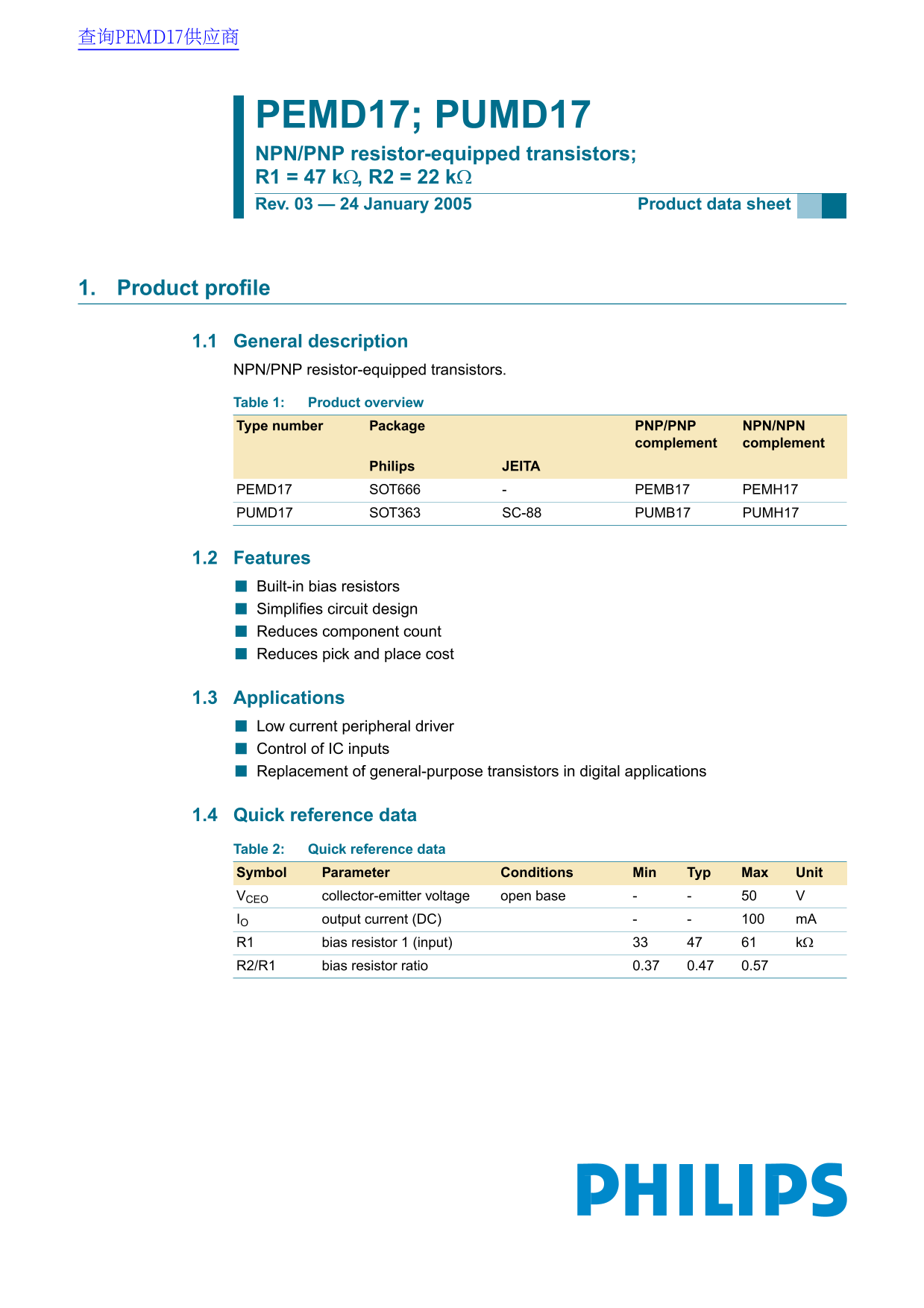
PEMD17; PUMD17 NPN/PNP resistor-equipped transistors; R1 = 47 kΩ, R2 = 22 kΩ Rev. 03 — 24 January 2005 Product data sheet

1. Product profile

1.1 General description NPN/PNP resistor-equipped transistors. Table 1: Product overview Type number Package PNP/PNP NPN/NPN

complement complement

Philips JEITA

PEMD17 SOT666 PEMB17 PEMH17 PUMD17 SOT363 SC-88 PUMB17 PUMH17

1.2 Features Built-in bias resistors Simplifies circuit design Reduces component count Reduces pick and place cost

1.3 Applications Low current peripheral driver Control of IC inputs Replacement of general-purpose transistors in digital applications

1.4 Quick reference data Table 2: Quick reference data Symbol Parameter Conditions Min Typ Max Unit

VCEO collector-emitter voltage open base IO output current (DC) m A

R1 bias resistor 1 (input) kΩ R2/R1 bias resistor ratio 0.37 0.47 0.57

Page Summary Contents For PHILIPS PUMD17 Data Sheet

Page 1 查询PEMD17供应商 PEMD17; PUMD17 NPN/PNP resistor-equipped transistors; R1 = 47 kΩ, R2 = 22 kΩ Rev. 03 — 24 January 2005 Product data sheet 1. Product profile 1.1 General description NPN/PNP resistor-equipp...
Page 2 Philips Semiconductors PEMD17; PUMD17 NPN/PNP resistor-equipped transistors; R1 = 47 kΩ, R2 = 22 kΩ 2. Pinning information Table 3: Pinning Pin Description Simplified outline Symbol GND (emitter) TR1 ...
Page 3 Philips Semiconductors PEMD17; PUMD17 NPN/PNP resistor-equipped transistors; R1 = 47 kΩ, R2 = 22 kΩ 5. Limiting values Table 6: Limiting values In accordance with the Absolute Maximum Rating System (I...
Page 4 Philips Semiconductors PEMD17; PUMD17 NPN/PNP resistor-equipped transistors; R1 = 47 kΩ, R2 = 22 kΩ 6. Thermal characteristics Table 7: Thermal characteristics Symbol Parameter Conditions Min Typ Max ...
Page 5 Philips Semiconductors PEMD17; PUMD17 NPN/PNP resistor-equipped transistors; R1 = 47 kΩ, R2 = 22 kΩ 006aaa184 006aaa185 VCEsat (3) (m V) IC (m A) IC (m A) VCE = 5 V IC/IB = 20 (1) Tamb = 100 °C (1) Ta...
Page 6 Philips Semiconductors PEMD17; PUMD17 NPN/PNP resistor-equipped transistors; R1 = 47 kΩ, R2 = 22 kΩ 006aaa208 006aaa209 VCEsat (1) IC (m A) IC (m A) VCE = −5 V IC/IB = 20 (1) Tamb = 100 °C (1) Tamb = ...
Page 7 Philips Semiconductors PEMD17; PUMD17 NPN/PNP resistor-equipped transistors; R1 = 47 kΩ, R2 = 22 kΩ 8. Package outline Plastic surface mounted package; 6 leads SOT363 pin 1 index e1 BMbp Lp detail X s...
Page 8 Philips Semiconductors PEMD17; PUMD17 NPN/PNP resistor-equipped transistors; R1 = 47 kΩ, R2 = 22 kΩ Plastic surface mounted package; 6 leads SOT666 pin 1 index e1 bp detail X scale DIMENSIONS (mm are ...
Page 9 Philips Semiconductors PEMD17; PUMD17 NPN/PNP resistor-equipped transistors; R1 = 47 kΩ, R2 = 22 kΩ 9. Packing information Table 9: Packing methods The indicated -xxx are the last three digits of the ...
Page 10 Philips Semiconductors PEMD17; PUMD17 NPN/PNP resistor-equipped transistors; R1 = 47 kΩ, R2 = 22 kΩ 10. Revision history Table 10: Revision history Document ID Release date Data sheet status Change no...
Page 11 Philips Semiconductors PEMD17; PUMD17 NPN/PNP resistor-equipped transistors; R1 = 47 kΩ, R2 = 22 kΩ 11. Data sheet status Level Data sheet status Product status Definition Objective data Development T...
Page 12 Philips Semiconductors PEMD17; PUMD17 NPN/PNP resistor-equipped transistors; R1 = 47 kΩ, R2 = 22 kΩ 15. Contents Product profile . . . . . . . . . . . . . . . . . . . . . . . . . . 1.1 General descrip...

Manual Details

Brand Philips
Pages 12
File Size 52.52 KB
Published July 04, 2026
0 views

Enter the captcha to get the download link:

captcha

Frequently Asked Questions

What is the primary benefit of using these resistor-equipped transistors?

They simplify circuit design by including built-in bias resistors, which reduces component count.

What is the maximum rated DC output current (collector-emitter)?

The standard maximum continuous collector-emitter output current is 100 mA.

What are the recommended environmental operating limits?

The device can operate in an ambient temperature range from -65°C to +150°C.

How should I ensure correct thermal dissipation when mounting these components?

For accurate power ratings, mount them on a FR4 printed-circuit board using single-sided copper standard footprint.