Page 1
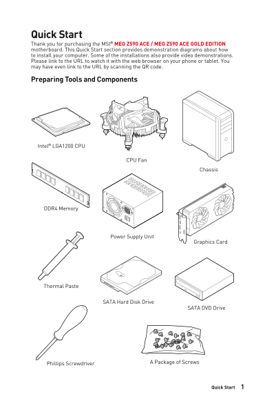
Quick Start Thank you for purchasing the MSI® MEG Z590 ACE / MEG Z590 ACE GOLD EDITION motherboard. This Quick Start section provides demonstration diagrams about how to install your computer. Some of...
Page 2
Safety Information The components included in this package are prone to damage from electrostatic discharge (ESD). Please adhere to the following instructions to ensure successful computer assembly. E...
Page 3
Case stand-off notification Before installing the motherboard into the case, install first the necessary mounting stand-off required for a motherboard on the mounting plate in the case. To prevent dam...
Page 4
Installing a Processor https://youtu.be/4ce91YC3Oww Quick Start
Page 5
Installing DDR4 memory http://youtu.be/T03a Dr JPy Qs DIMMA1 DIMMA2 DIMMA2 DIMMA2 DIMMB2 DIMMB1 DIMMB2 5Quick Start
Page 6
Connecting the Front Panel Header T S SW http://youtu.be/DPELId VNZUI SE RE WER PO HD D L ED Power LED Power Switch RE SET SW Reserved HDD LED Reset Switch HDD LED + Power LED + HDD LED - Power LED - ...
Page 7
Installing the Motherboard https://youtu.be/w WI6Qt51Wnc Torque: 3 kgf·cm* *3 kgf·cm = 0.3 N·m = 2.6 lbf·in 7Quick Start
Page 8
Connecting the Power Connectors http://youtu.be/gk DYy R_83I4 ATX_PWR1 CPU_PWR2 PCIE_PWR1 CPU_PWR1 Quick Start
Page 9
Installing SATA Drives http://youtu.be/RZs Mpqxythc 9Quick Start
Page 10
Installing a Graphics Card http://youtu.be/m G0GZpr9w_A Quick Start
Page 11
Connecting Peripheral Devices 11Quick Start
Page 12
Power On Quick Start
Page 13
Contents Quick Start ............................................................................................................. Preparing Tools and Components..........................................
Page 14
T_SEN1: Thermal Sensor Connector ................................................................... V-Check Points Lite ..................................................................................
Page 15
Resetting BIOS ...................................................................................................... Updating BIOS .......................................................................
Page 16
Specifications Supports 10th Gen Intel® Core™ Processors, 11th Gen Intel® Core™ Processors, Pentium® Gold and Celeron® Processors* Processor socket LGA1200 * Please go to intel.com for compatibility i...
Page 17
Continued from previous column Intel® JHL8540 Thunderbolt™ 4 Controller 2x Thunderbolt™ 4 (USB-C) ports on the back panel Support up to 40Gbps transfer rate with Thunderbolt devices Support up to 20Gb...
Page 18
Continued from previous column Intel® Z590 Chipset 3x USB 3.2 Gen 2 10Gbps ports (2 Type-A port on the back panel, 1 Type-C internal connector) 6x USB 3.2 Gen 1 5Gbps ports (4 Type-A port on the back ...
Page 19
Continued from previous column 1x 24-pin ATX main power connector 2x 8-pin ATX 12V power connectors 1x 6-pin PCIE power connector 6x SATA 6Gb/s connectors 4x M.2 slots (M-Key) 1x USB 3.2 Gen 2 10Gbps ...
Page 20
Continued from previous column 1x Clear CMOS button 1x Flash BIOS button 4x USB 3.2 Gen 1 5Gbps Type-A ports 2x USB 2.0 Type-A ports 1x HDMI port 1x LAN (RJ45) port Back Panel Connectors 2x USB 3.2 Ge...
Page 21
Continued from previous column Duet Display MSI Sound Tune Gaming Mode Creator Mode Mystic Light Ambient Link LAN Manager (Powered By c Fos Speed) MSI Center Features User Scenario Monitor Frozr AI Co...
Page 22
Continued from previous column LED Mystic Light Mystic Light Extension (RGB) Mystic Light Extension (RAINBOW) Mystic Light Extension (CORSAIR) Mystic Light SYNC Ambient Link EZ LED Control EZ DEBUG LE...
Page 23
Continued from previous column Protection DDR4 Steel Armor PCI-E Steel Armor Pre-installed I/O Shield Experience Smart Button Special Features MSI Center Duet Display Frozr AI Cooling Click BIOS 5 Sys...
Page 24
Package contents Please check the contents of your motherboard package. It should contain: Motherboard MEG Z590 ACE / MEG Z590 ACE GOLD EDITION User manual Documentation Quick guide Quick installation...
Page 25
Block Diagram PCI_E1 PCIe x16 PCI_E3 DDR4 2Channel PCIe x8 DIMM A1,A2 DIMM B1,B2 DMI x8 PCI_E2 USB 3.2 Gen 2 10Gbps PCI_E4 USB 3.2 Gen 1 5Gbps M2_3SATA5/6 USB 2.0 M2_4PCI_E5 USB 2.0 Hub-GL850G Thunder...
Page 26
Rear I/O Panel Flash BIOS Port Thunderbolt 4 Audio Ports USB 2.0 2.5 Gbps (USB-C) Clear CMOS button Flash BIOS Mini Display Port Optical Button Input (for Thunderbolt S/PDIF-Out passthrough) USB 3.2 G...
Page 27
Realtek Audio Console After Realtek Audio Console is installed. You can use it to change sound settings to get better sound experience. Application Enhancement Device Selection Main Volume Jack Status...
Page 28
Audio jacks to headphone and microphone diagram Audio jacks to stereo speakers diagram AUDIO INPUT Audio jacks to 7.1-channel speakers diagram AUDIO INPUT Side Center/ Subwoofer Rear I/O Panel
Page 29
Installing Antennas 1. Combine the antenna with the base. 2. Screw two antenna cables tight to the Wi Fi antenna connectors as shown. 3. Place the antenna as high as possible. 29Rear I/O Panel
Page 30
Connecting Thunderbolt Devices via Daisy-chain Daisy-chain is a method of connecting multiple devices to a PC with only one output terminal. Daisy-chain allows you to connect multiple thunderbolt devi...
Page 31
Overview of Components CPU_FAN1 Processor PUMP_FAN1 Socket JCORSAIR1 JRAINBOW2 CPU_PWR2 CPU_PWR1 DIMMA1 DIMMA2 DIMMB1 DIMMB2 SYS_FAN5 ATX_PWR1 M2_1 JUSB4 SYS_FAN1 PCI_E1 JUSB3 M2_3 SATA▼1▲2 PCI_E2 SAT...
Page 32
Component Contents Port Name Port Type Page BIOS_SW1 Multi-BIOS Switch CPU_FAN1, PUMP_FAN1, Fan Connectors SYS_FAN1~6 CPU_PWR1~2, ATX_PWR1, Power Connectors PCIE_PWR1 CPU Socket LGA1200 CPU Socket DIM...
Page 33
CPU Socket Distance from the center of the CPU to the nearest DIMM slot. 50.53 mm Introduction to the LGA1200 CPU The surface of the LGA1200 CPU has two notches and a golden triangle to assist in corr...
Page 34
DIMM Slots DIMMA1 DIMMB1 Channel A Channel B DIMMA2 DIMMB2 Memory module installation recommendation DIMMA1 DIMMA2 DIMMA2 DIMMB1DIMMA2 DIMMB2 DIMMB2 Important Always insert memory modules in the DIMMA...
Page 35
PCI_E1~5: PCIe Expansion Slots PCI_E1: PCIe 4.0 x16 (From CPU) PCI_E2: PCIe 3.0 x1 (From Z590 chipset) PCI_E3: PCIe 4.0 x8 (From CPU) PCI_E4: PCIe 3.0 x1 (From Z590 chipset) PCI_E5: PCIe 3.0 x4 (From ...
Page 36
Important If you install a large and heavy graphics card, you need to use a tool such as MSI Graphics Card Bolster to support its weight to prevent deformation of the slot. For a single PCIe x16 expan...
Page 37
M2_1~4: M.2 Slots (Key M) Video Demonstration Watch the video to learn how to Install M.2 SSD. https://youtu.be/2Ue WMgjwog U Important Intel® RST only supports PCIe M.2 SSD with UEFI ROM. Intel® Opta...
Page 38
3. Secure the supplied M.2 standoff according to your M.2 SSD length if need. 4. Insert your M.2 SSD into the M.2 slot at a 30-degree angle. 5. Secure the M.2 SSD in place with the supplied M.2 8.5H s...
Page 39
SATA1~6: SATA 6Gb/s Connectors These connectors are SATA 6Gb/s interface ports. Each connector can connect to one SATA device. SATA2 SATA1 SATA4 SATA3 SATA6 SATA5 Important Please do not fold the SATA...
Page 40
JFP1, JFP2: Front Panel Connectors These connectors connect to the switches and LEDs on the front panel. Buzzer 1JFP2 Speaker Speaker - Buzzer + Buzzer - Speaker + Power LED Power Switch Reserved HDD ...