Page 1
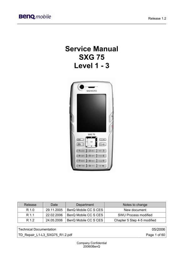
Release 1.2 Service Manual SXG 75 Level 1 - 3 Release Date Department Notes to change R 1.0 29.11.2005 Ben Q Mobile CC S CES New document R 1.1 22.02.2006 Ben Q Mobile CC S CES SWU Process modified R ...
Page 2
Release 1.2 Table of Content 1 Key Features..............................................................................................................................3 2 SXG75 Interface to Accessor...
Page 3
Release 1.2 1 Key Features Battery • Li – Ion Battery Pack • Nominal Capacity: 1000 m Ah • GSM Capacity: 980 m Ah Stand – by Time • Up to 420h Talk Time • GSM: Up to 3,6hr • WCDMA: Up to 3,1hr SIM Car...
Page 4
Release 1.2 Acoustics • Combined handsfree/ringer speaker at rear side of phone, next to camera • Dedicated ear piece speaker, allowing small dimensions as not needed as handfree speaker • Uni - direc...
Page 5
Release 1.2 2 SXG75 Interface to Accessories The phone has the following compatible interfaces to accessories: - electrically by the Lumberg I/O connector (Lumberg slim) - antenna connection by courte...
Page 6
Release 1.2 3 Unit Description of SXG75 The SXG75 is a brick phone with 2 integrated cameras for video telephony and photo applications. The phone has two different acoustic modules one for receiver m...
Page 7
Release 1.2 4 Exploded View of SXG75 Upper Case Side - Keys Side Cover Keypad Flexible PCB UMTS Camera Cover Display - Module UMTS - Camera PCB Camera Vibramotor MMC - Holder Microphone Lower Case Ear...
Page 8
Release 1.2 5 Disassembly of SXG75 All repairs as well as disassembling and assembling have to be carried out in an ESD protected environment and with ESD protected equipment/tools. For all activities...
Page 9
Release 1.2 Step 2 Remove Rear Cover by pushing it with both thumbs forwards. Step 3 Remove screws with Torque - Screwdriver. Screws size: T5+ Step 4 Remove Upper Case by using Alternative Opening Too...
Page 10
Release 1.2 Step 5 Step 6 Step 7 Disconnect Flex Cable from PCB by using Tweezers carefully. Technical Documentation 05/2006 TD_Repair_L1-L3_SXG75_R1.2.pdf Page 10 of 60 Company Confidential 2006©Ben ...
Page 11
Release 1.2 Step 8 Remove MMC Holder by pushing it with Alternative Opening Tool outside the frame. Step 9 Use Alternative Opening Tool to remove PCB from Lower Case carefully. Step 10 To avoid scratc...
Page 12
Release 1.2 Step 11 Remove Flexible PCB with Alternative Opening Tool carefully. The Loudspeaker is not removable. Step 12 Step 13 Remove Side keys by using Tweezers. Technical Documentation 05/2006 T...
Page 13
Release 1.2 Step 14 Step 15 Use Tweezers to remove Keypad. Step 16 Remove Microphone by using Tweezers carefully. Be careful with the spring contacts of the Microphone! Technical Documentation 05/2006...
Page 14
Release 1.2 Step 17 Remove Vibramotor by using Tweezers carefully. Step 18 Remove Earphone by using Tweezers carefully. Step 19 Use Alternative Opening Tool to remove Camera Cover carefully. Technical...
Page 15
Release 1.2 Step 20 Step 21 Step 22 Disconnect Flex Cable from PCB with Tweezers. Technical Documentation 05/2006 TD_Repair_L1-L3_SXG75_R1.2.pdf Page 15 of 60 Company Confidential 2006©Ben Q
Page 16
Release 1.2 Step 23 Remove Display from PCB by using Alternative Opening Tool very carefully. Step 24 Put the Camera Ejector Jig professional through the four edges between the Camera and the Camera C...
Page 17
Release 1.2 Step 26 Step 27 Remove UMTS Camera with Alternative Opening Tool very carefully. Overview Lower Parts Overview Upper Parts Upper Case Display Flexible PCB Battery Rear Cover Lower Case Mic...
Page 18
Release 1.2 6 Assembly of SXG75 Step 1 Assemble UMTS - Camera by using Tweezers. Step 2 Connect the UMTS – Camera with PCB by using Tweezers. Step 3 Use Tweezers to assemble Camera Cover. Technical Do...
Page 19
Release 1.2 Step 4 Assemble Camera by using Camera Ejector Step 5 Assemble Display by fixing it in the given frame. Take care of the Display! Step 6 Assemble Camera Cover. Technical Documentation 05/2...
Page 20
Release 1.2 Step 7 Step 8 Assemble Earphone by using Tweezers carefully. Step 9 Assemble Vibramotor by using Tweezers carefully. Technical Documentation 05/2006 TD_Repair_L1-L3_SXG75_R1.2.pdf Page 20 ...
Page 21
Release 1.2 Step 10 Assemble Microphone by using Tweezers. Be careful with the spring contacts of the Microphone! Step 11 Assemble Side keys with Tweezers. Step 12 Technical Documentation 05/2006 TD_R...
Page 22
Release 1.2 Step 13 Use Tweezers to assemble Keypad. Step 14 Assemble Flexible PCB by using Tweezers. Push it carefully with both thumbs in the Upper Case. Step 15 Before assembling PCB in the Upper C...
Page 23
Release 1.2 Step 16 Step 17 Assemble PCB by fixing it in the Upper Case. Step 18 To assemble PCB connect it with Flex Cable. Technical Documentation 05/2006 TD_Repair_L1-L3_SXG75_R1.2.pdf Page 23 of 6...
Page 24
Release 1.2 Step 19 Assemble MMC holder by pushing it in the given frame. Step 20 Fix the Upper Case on the before assembled Lower Case and PCB. Step 21 Technical Documentation 05/2006 TD_Repair_L1-L3...
Page 25
Release 1.2 Step 22 Place screws by using Torque – Screwdriver. Top screw (Antenna): Screw size: T5+ Torque: 17 c Nm Centre/ Bottom screws: Screw size: T5+ Torque: 20 c Nm Step 23 Assemble Rear Cover....
Page 26
Release 1.2 Step 25 Assemble Battery Cover. Technical Documentation 05/2006 TD_Repair_L1-L3_SXG75_R1.2.pdf Page 26 of 60 Company Confidential 2006©Ben Q
Page 27
Release 1.2 7 Ben Q Service Equipment User Manual Introduction Every LSO repairing Ben Q handset must ensure that the quality standards are observed. Ben Q has developed an automatic testing system th...
Page 28
Release 1.2 8 GRT Software: Functionality Configuration Note: Not implemented in GRT Version 3.x. For Software Update please use the tool 3GSWUP_FU. Manual and Software are available in the Technical ...
Page 29
Release 1.2 Step 3: Connect to GRM Server • Choose in the section „GRM” the „Connect to GRM Database“ functionality Enter your GRT-Username and Password into this fields 1 Activate always both boxes i...
Page 30
Release 1.2 9 GRT Software: Regular Usage Step 1: Select the section SWUpdate Step 2: Choose the area you want to work with • Personal Repair Personal Repair is always accessible. Basis for the decisi...
Page 31
Release 1.2 9.1 Window explanation This general explanation is valid for all SW-Update channels (Personal Repair, Operator SWAP, Operator SWUpdate) After using „Check Variant“ Phone IMEI- Number will ...
Page 32
Release 1.2 9.2 Case 1: Personal Repair (green) Step 1: Carry out step 1 – 4 to start SW-Update. Select the mobile phone CPU type Start SW-Update Choose if customer data shall be erased. If “Yes” acti...
Page 33
Release 1.2 9.3 Case 2: Operator SWAP (red) Step 1: Carry out step 1 – 4 to start SW-Update. Select the mobile phone CPU type Start SW-Update Choose if customer data shall be erased. If “Yes” activate...
Page 34
Release 1.2 9.4 Case 3 Operator SWUpdate (blue) Step 1: Carry out step 1 – 4 to start SW-Update. Select the mobile phone CPU type Start SW-Update Choose if customer data shall be erased. If “Yes” acti...
Page 35
Release 1.2 10 JPICS (Java based Product Information Controlling System) Overview The following functions are available for the LSO: • General mobile information • Generate PINCODE • Generate SIMLOCK ...
Page 36
Release 1.2 The access to the JPICS server which is located in Kamp – Lintfort is protected by chip card and in addition using secure socket layer (SSL) connection. The JPICS server is only available ...
Page 37
Release 1.2 Installation overview The following installation description assumes that a web browser is already installed. JPICS is tested with the following browsers: 1. Internet Explorer Version 5.5 ...
Page 38
Release 1.2 Generate Codes In the JPICS application you can choose to generate: • Masterphone codes • Simlock – Unlock – Codes Masterphone codes The Masterphone code is used to unlock blocked mobiles....
Page 39
Release 1.2 Simlock – Unlock – Code The Simlock – Unlock – Codes can only be generated if the following conditions are given: • Mobile must have an active Simlock inside. • The user must be given the ...
Page 40
Release 1.2 Printing IMEI label The module “printing IMEI label” offers the possibility to re-print IMEI labels for mobiles again. You are able to print 1 label in just one step. To prevent that misal...