Page 1
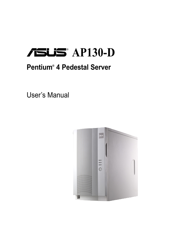
AP130-D Pentium® 4 Pedestal Server User’s Manual
Page 2
Disclaimer/Copyrights No part of this manual, including the products and software described in it, may be reproduced, transmitted, transcribed, stored in a retrieval system, or translated into any lan...
Page 3
Contents Disclaimer/Copyrights ASUS Contact Information FCC/CDC Statements Safety Precautions Introduction: About This Manual Audience Contents Conventions References System Package Contents Chapter 1...
Page 4
Contents 2.5 Install a Hard Disk Drive Remove the HDD/Floppy Cage Install the HDD Connect the Cables 2.6 Replace the Cover Re-install the Cover Chapter 3: Powering Up 3.1 Getting Started Connect a Mon...
Page 5
ASUS Contact Information ASUSTe K COMPUTER INC. (Asia-Pacific) Address: 150 Li-Te Road, Peitou, Taipei, Taiwan 112 General Tel: +886-2-2894-3447 General Fax: +886-2-2894-3449 General Email: info@asus....
Page 6
FCC/CDC Statements Federal Communications Commission Statement This device complies with FCC Rules Part 15. Operation is subject to the following two conditions: This device may not cause harmful inte...
Page 7
Safety Precautions Electrical Safety IMPORTANT Before installing or removing signal cables, ensure that the power cables for the system unit and all attached devices are unplugged. To prevent electric...
Page 9
Introduction of this document. This part includes the target audience, chapter description, and conventions used. It also lists other sources of information that are not contained in this manual. is a...
Page 10
Audience This manual is intended for system integrators, and experienced users with at least basic knowledge of configuring an entry-level server. Contents This manual contains the following parts: 1....
Page 11
Conventions Symbols To make sure that you perform certain tasks properly, take note of the following symbols used throughout this manual. WARNING: Information to prevent injury to yourself when trying...
Page 12
System Package Contents The following checklist enumerates the components included in the standard system package. 1) ASUS AS11 chassis 2) ASUS P4B266-M motherboard 3) 200W ATX power supply 4) 52X CD-...
Page 13
Chapter 1 This chapter describes the general features of the AP130-D server. It includes sections on front panel, rear panel, and internal features of the server. ys te ve rv ie 13ASUS AP130-D Pedesta...
Page 14
1.1 System Features The ASUS AP130-D is a stylish barebone server featuring the ASUS P4B266-M motherboard. The server supports the Intel® Pentium® 4 478/ Northwood processor, and includes the latest I...
Page 15
1.2 Front Panel Features The AP130-D front panel is designed with a door secured by a keylock. When locked, the door prevents unauthorized access to the front panel components. Front Panel Door Keyloc...
Page 16
1.3 Rear Panel Features The AP130-D rear panel includes the external I/O ports. The following picture shows the cable connectors and the devices that you connect to the ports. PS/2 KB AC Power PS/2 Mo...
Page 17
1.4 Internal Features The standard components inside the AP130-D server include the motherboard, power supply, floppy and CD-ROM drives, and cables. The picture below shows the standard components of ...
Page 18
Chapter 1: System Overview
Page 19
Chapter 2 This chapter describes the hardware setup procedures that you have to perform when installing system components. ar ar et 19ASUS AP130-D Pedestal Server
Page 20
2.1 Remove the Chassis Cover Unlock the side cover Two thumbscrews secure the removable side panel cover. Turn these screws counter-clockwise to release the cover. The screws are attached to the cover...
Page 21
2.2 Motherboard Placement NOTE The motherboard and other internal components of the AP130-D server are already installed as indicated in section “1.4 Internal Features”. Refer to the motherboard user’...
Page 22
2.3 Install a CPU The 478-pin Zero Insertion Force (ZIF) socket on the P4B266-M motherboard supports an Intel Pentium 4 processor. This section tells you how to install a CPU. Refer to the motherboard...
Page 23
Unlock the CPU Socket Unlock the socket by pressing the lever sideways then lifting it up to a 90°-100° angle. Socket Lever 90 - Insert the CPU 1. Position the CPU above the socket such that its marke...
Page 24
Install the Fan Heatsink Assembly 1. Align and snap the hooks of a retention bracket into the holes of the retention module base. Make sure that the arrow on the bracket points inward. 2. Follow step ...
Page 25
4. Orient the fan heatsink assembly with the fan cable nearest the CPU fan connector on the motherboard (marked CPU_FAN). 5. Carefully place the fan heatsink assembly on top of the CPU. Make sure that...
Page 26
2.4 Install System Memory DIMM Sockets Location The motherboard has two Dual Inline Memory Module (DIMM) sockets that support up to 2GB system memory using PC2100/ PC1600 DDR DIMMs. DDR DIMM sockets I...
Page 27
2.5 Install a Hard Disk Drive Remove the HDD/Floppy Cage 1. Remove the screw that secures the HDD/floppy cage. Make sure to disconnect the floppy cable from the floppy disk before removing the cage ou...
Page 28
Install the HDD 1. Insert the HDD into the cage (label side up) until the holes on the HDD align with the holes on the cage. 2. Secure the HDD with four screws (two on each side). 3. Replace the cage ...
Page 29
2.6 Replace the Cover Re-install the Cover 1. Position the cover in place, aligning the tabs on the inner side of the cover to the rail holes on the chassis edge. 2. Slide the cover toward the front p...
Page 30
Chapter 2: Hardware Setup
Page 31
Chapter 3 This chapter tells how to get started with the AP130-D server. Powering up the server basically includes connecting the cables and turning power on. er in 31ASUS AP130-D Pedestal Server
Page 32
3.1 Getting Started Make sure that you have completed the basic system installations in Chapter 2, then follow these steps to start up the server. Connect a Monitor Connect a monitor by plugging hte m...
Page 33
Appendix A This appendix gives information on the 200W switching power supply that comes with the AP130-D server. er ly 33ASUS AP130-D Pedestal Server
Page 34
A.1 General Description The server comes with a 200W ATX power supply with universal AC input that includes PFC and ATX-compliant output cables and connectors. The power supply has an internal cooling...
Page 35
A.2 Specifications Input Characteristics Input Voltage Range Min Nom Max Range 1 90V 115V 140V Range 2 180V 230V 264V Input Frequency Range 43 Hz to 66 Hz Maximum Input ac Current 5A max at 115Vac 3A ...
Page 36
Appendix A: Power Supply
Page 37
Appendix B This appendix lists the common problems that you may encounter while using the AP130-D server. It lists the possible causes of the problems and offers solutions. You may refer to this part ...
Page 38
B.1 Simple Fixes NOTE Some problems that you may encounter are not due to defects on the system or the components. These problems only requires simple troubleshooting actions that you can perform by y...
Page 39
Problem Action The system continuously beeps 1. Check the memory modules after it was turned on and make sure you installed the DIMMs the system supports. 2. Make sure that the DIMMs are properly inst...
Page 40
Appendix B: Troubleshooting