# A B C D E F G H I J K L M N O P Q R S T U V W X Y Z

ADMD Analog Devices ADM1178 Data Sheet Manual

Summary

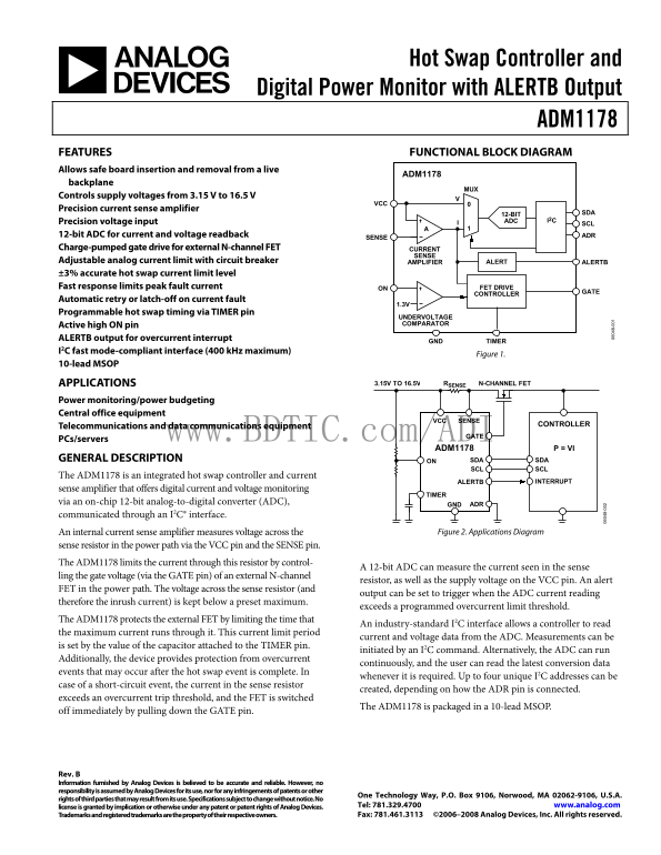
The ADM1178 is a high-precision integrated hot swap controller and digital power monitor designed for safely managing board insertion and removal in live backplanes. It provides accurate monitoring of both current and voltage across multiple supply rails (3.15V to 16.5V). This resource guides users through the device's functional block diagrams, advanced overcurrent protection features, and serial bus communication. The ADM1178 is essential for power budgeting and reliability in demanding applications, including central office equipment, telecommunications gear, and data center servers.
📄 Preview 📖 Table of Contents Contents PAGE OF 24

Page 1 Text Content

Hot Swap Controller and

Digital Power Monitor with ALERTB Output

ADM1178 FEATURES FUNCTIONAL BLOCK DIAGRAM Allows safe board insertion and removal from a live

ADM1178

backplane

Controls supply voltages from 3.15 V to 16.5 V

Precision current sense amplifier

12-BIT SDA

Precision voltage input ADC I2C

12-bit ADC for current and voltage readback ADR

SENSE

Charge-pumped gate drive for external N-channel FET CURRENT

SENSE

Adjustable analog current limit with circuit breaker AMPLIFIER ALERT ALERTB ±3% accurate hot swap current limit level Fast response limits peak fault current ON FET DRIVE

CONTROLLER

Automatic retry or latch-off on current fault

Programmable hot swap timing via TIMER pin

UNDERVOLTAGE Active high ON pin COMPARATOR

ALERTB output for overcurrent interrupt

GND TIMER

I2C fast mode-compliant interface (400 k Hz maximum)

Figure 1.

10-lead MSOP

APPLICATIONS 3.15V TO 16.5V RSENSE N-CHANNEL FET

Power monitoring/power budgeting Central office equipment

SENSEVCC

Telecommunications and data communications equipment CONTROLLER

www.BDTIC.com/ADI GATE

PCs/servers

ADM1178 P = VI

GENERAL DESCRIPTION ON SDA SDA

SCL SCL

The ADM1178 is an integrated hot swap controller and current

INTERRUPTALERTB

sense amplifier that offers digital current and voltage monitoring

TIMER

via an on-chip 12-bit analog-to-digital converter (ADC), ADR

communicated through an I2C® interface.

An internal current sense amplifier measures voltage across the Figure 2. Applications Diagram

sense resistor in the power path via the VCC pin and the SENSE pin. The ADM1178 limits the current through this resistor by control-

A 12-bit ADC can measure the current seen in the sense

ling the gate voltage (via the GATE pin) of an external N-channel

resistor, as well as the supply voltage on the VCC pin. An alert

FET in the power path. The voltage across the sense resistor (and

output can be set to trigger when the ADC current reading

therefore the inrush current) is kept below a preset maximum. 8-

exceeds a programmed overcurrent limit threshold.

The ADM1178 protects the external FET by limiting the time that

An industry-standard I2C interface allows a controller to read

the maximum current runs through it. This current limit period

current and voltage data from the ADC. Measurements can be

is set by the value of the capacitor attached to the TIMER pin.

initiated by an I2C command. Alternatively, the ADC can run

Additionally, the device provides protection from overcurrent

continuously, and the user can read the latest conversion data

events that may occur after the hot swap event is complete. In

whenever it is required. Up to four unique I2C addresses can be

case of a short-circuit event, the current in the sense resistor

created, depending on how the ADR pin is connected.

exceeds an overcurrent trip threshold, and the FET is switched

The ADM1178 is packaged in a 10-lead MSOP.

off immediately by pulling down the GATE pin.

Rev. B Information furnished by Analog Devices is believed to be accurate and reliable. However, no responsibility is assumed by Analog Devices for its use, nor for any infringements of patents or other

One Technology Way, P.O. Box 9106, Norwood, MA 02062-9106, U.S.A.

rights of third parties that may result from its use. Specifications subject to change without notice. No

license is granted by implication or otherwise under any patent or patent rights of Analog Devices. Tel: 781.329.4700 www.analog.com Trademarks and registered trademarks are the property of their respective owners. Fax: 781.461.3113 ©2006–2008 Analog Devices, Inc. All rights reserved.

Page Summary Contents For ADMD Analog Devices ADM1178 Data Sheet Manual

Page 1 Hot Swap Controller and Digital Power Monitor with ALERTB Output ADM1178 FEATURES FUNCTIONAL BLOCK DIAGRAM Allows safe board insertion and removal from a live ADM1178 backplane Controls supply voltage...
Page 2 ADM1178 TABLE OF CONTENTS Features Initial Timing Cycle Applications....................................................................................... Hot Swap Retry Cycle on the ADM1178-1..........
Page 3 ADM1178 SPECIFICATIONS VCC = 3.15 V to 16.5 V, TA = −40°C to +85°C, typical values at TA = 25°C, unless otherwise noted. Table 1. Parameter Min Typ Max Unit Conditions VCC PIN Operating Voltage Range,...
Page 4 ADM1178 Parameter Min Typ Max Unit Conditions MONITORING ACCURACY1 Current Sense Absolute Accuracy 0°C to +70°C −1.45 +1.45 % VSENSE = 75 m V −1.8 +1.8 % VSENSE = 50 m V −2.8 +2.8 % VSENSE = 25 m V −5...
Page 5 ADM1178 Parameter Min Typ Max Unit Conditions Low Period of the SCL Clock 600 ns High Period of the SCL Clock 1300 ns ADC Conversion Time4 150 μs Fast Overcurrent Response Time5 4 10 μs Setup Time for...
Page 6 ADM1178 ABSOLUTE MAXIMUM RATINGS THERMAL CHARACTERISTICS Table 2. θJA is specified for the worst-case conditions, that is, a device Parameter Rating soldered in a circuit board for surface-mount packa...
Page 7 ADM1178 PIN CONFIGURATION AND FUNCTION DESCRIPTIONS VCC ALERTB10 SENSE GATE9 ADM1178 ON TOP VIEW ADR8 (Not to Scale) GND SDA7 TIMER SCL6 Figure 3. Pin Configuration Table 4. Pin Function Descriptions ...
Page 8 TE (µ IV VO LT (V (m ADM1178 TYPICAL PERFORMANCE CHARACTERISTICS VCC (V) TEMPERATURE (°C) Figure 4. Supply Current vs. Supply Voltage Figure 7. Supply Current vs. Temperature (Gate On) TE (µ IV VO LT ...
Page 9 ADM1178 (m TE (µ (m TE TE VCC (V) VCC (V)06 Figure 10. Gate Pull-Down Current vs. Supply Voltage at VGATE = 5 V Figure 13. Timer Threshold vs. Supply Voltage TI ER ES LD (V TI ER ES LD (V TE IM (m s) ...
Page 10 IM ER (µ IM ER (µ (µ IM ER ADM1178 VCC (V) TEMPERATURE (°C) Figure 16. Timer Pull-Up Current (Initial Cycle) vs. Supply Voltage Figure 19. Timer Pull-Up Current (Initial Cycle) vs. Temperature IM ER (...
Page 11 ADM1178 VO LT (m V) IM (m V) VCC (V) CODE Figure 22. Circuit Breaker Limit Voltage vs. Supply Voltage Figure 25. ADC Noise with Current Channel, Midcode Input, and 1000 Reads VOCFAST IT PE (1 EA S) IT...
Page 12 LE TB TP LO (V (L SB IN (L SB ADM1178 CODE VCC (V) Figure 28. INL for ADC Figure 31. ALERTB Output Low Voltage vs. Supply @ 1 m A 8- 8- 8- LE TB TP LO (V LE TB TP LO (V –2 www.BDTIC.com/ADI 0.4 ILOAD ...
Page 13 ADM1178 OVERVIEW OF THE HOT SWAP FUNCTION When circuit boards are inserted into a live backplane, discharged The ADM1178-2 is immediately latched off and attempts a hot supply bypass capacitors draw l...
Page 14 ADM1178 GATE AND TIMER FUNCTIONS DURING CALCULATING CURRENT LIMITS AND FAULT A HOT SWAP OPERATION CURRENT LIMIT TIME During hot insertion of a board onto a live supply rail at VCC, The nominal linear ...
Page 15 ADM1178 When the initial timing cycle terminates, the device is ready to start a hot swap operation (assuming that the ON pin is asserted). In the example shown in Figure 33, the ON pin is asserted at...
Page 16 ADM1178 VOLTAGE AND CURRENT READBACK In addition to providing hot swap functionality, the ADM1178 The peripheral whose address corresponds to the transmitted contains the components to allow voltage a...
Page 17 ADM1178 SDA 0ADRBADRA1 R/W D7 D6 D5 D4 D3 D2 D1 D0 START BY MASTER ACKNOWLEDGE BY ACKNOWLEDGE BY SLAVE SLAVEFRAME 1 FRAME 2 SLAVE ADDRESS COMMAND CODE SCL (CONTINUED) (CONTINUED) ACKNOWLEDGE BY ACKNOW...
Page 18 ADM1178 WRITE AND READ OPERATIONS The I2C specification defines several protocols for different types of WRITE COMMAND BYTE read and write operations. The operations used in the ADM1178 In the write c...
Page 19 ADM1178 WRITE EXTENDED COMMAND BYTE In the write extended command byte operation, the master 7. The slave asserts an acknowledge on SDA. device writes to one of the three extended registers of the sla...
Page 20 ADM1178 READ VOLTAGE AND/OR CURRENT DATA BYTES For cases where the master is reading voltage only or current only, two data bytes are read and Step 7 and Step 8 are not required. Depending on how the ...
Page 21 ADM1178 Table 15. Status Byte Operations Bit Name Function 0 ADC_OC An ADC-based overcurrent comparison is detected on the last three conversions. 1 ADC_ALERT An ADC-based overcurrent trip has occurre...
Page 22 ADM1178 APPLICATIONS INFORMATION APPLICATIONS WAVEFORMS CH1 1.5A CH2 1.00V M40.0ms CH1 1.5A CH2 1.00V M10.0ms CH3 20.0V CH4 10.0V CH3 20.0V CH4 10.0V Figure 44. Inrush Current Control into 220 μF Load...
Page 23 ADM1178 ALERTB OUTPUT KELVIN SENSE RESISTOR CONNECTION The ALERTB output is an open-drain pin with 30 V tolerance. When using a low value sense resistor for high current meas- This output can be used ...
Page 24 ADM1178 OUTLINE DIMENSIONS PIN 1 0.50 BSC 0.95 0.85 1.10 MAX 0.75 0.33 SEATING 0.60 0.05 0.17 PLANE 0.40 COPLANARITY 0.10 COMPLIANT TO JEDEC STANDARDS MO-187-BA Figure 51. 10-Lead Mini Small Outline P...

Manual Details

Brand Analog Devices
Pages 24
File Size 696.24 KB
Published June 15, 2026
2 views

Enter the captcha to get the download link:

captcha

Frequently Asked Questions

What is the ADM1178 designed to monitor?

It monitors current and voltage in power paths, providing hot swap control and digital monitoring through an on-chip ADC.

How does the device protect against overcurrent?

It limits current by controlling an external N-channel FET and can trigger an alert if the current exceeds a programmed threshold.

Can the ADM1178 be used for power budgeting or sensing?

Yes, it is suitable for power monitoring/power budgeting in applications like central office equipment and data communications.

What are the available models for different operating conditions?

Models include the ADM1178-1 (Automatic Retry Version) and ADM1178-2 (Latched Off Version), both in 10-Lead MSOP packaging.