AD8274 Analog Devices Data Sheet Manual
Summary
Discover the AD8274, a high-performance difference amplifier designed for demanding signal integrity applications. Offering exceptional low distortion and robustness across both AC and DC signals, this component is ideal for professional audio, precise instrumentation building blocks, and industrial signal measurement up to ±36V single supply. This manual serves as a comprehensive guide, detailing the theory of operation, performance characteristics, optimal configurations, and diverse industrial/audio applications necessary for integration success.
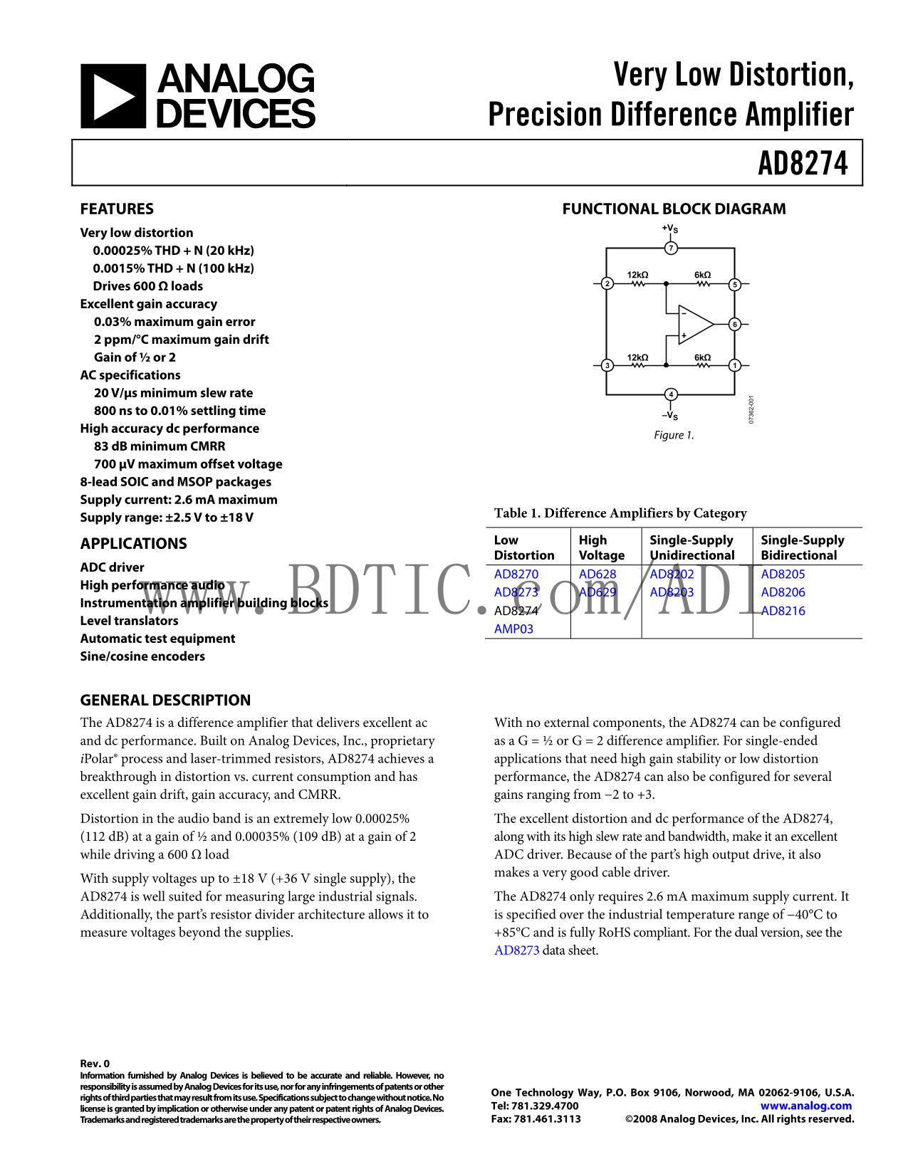
Page 1 Text Content
Very Low Distortion, Precision Difference Amplifier
AD8274 FEATURES FUNCTIONAL BLOCK DIAGRAM
Very low distortion 0.00025% THD + N (20 k Hz) 0.0015% THD + N (100 k Hz)
Drives 600 Ω loads Excellent gain accuracy 0.03% maximum gain error 2 ppm/°C maximum gain drift
Gain of ½ or 2 12kΩ 6kΩ
AC specifications 20 V/μs minimum slew rate 800 ns to 0.01% settling time
High accuracy dc performance
Figure 1.
83 d B minimum CMRR 700 μV maximum offset voltage 8-lead SOIC and MSOP packages Supply current: 2.6 m A maximum
Table 1. Difference Amplifiers by Category
Supply range: ±2.5 V to ±18 V
Low High Single-Supply Single-Supply
APPLICATIONS
Distortion Voltage Unidirectional Bidirectional
ADC driver
AD8270 AD628 AD8202 AD8205
High performance audio
AD8273 AD629 AD8203 AD8206
Instrumentation amplifier building blocks www.BDTIC.com/ADI
AD8274 AD8216
Level translators
AMP03
Automatic test equipment Sine/cosine encoders
GENERAL DESCRIPTION
The AD8274 is a difference amplifier that delivers excellent ac With no external components, the AD8274 can be configured and dc performance. Built on Analog Devices, Inc., proprietary as a G = ½ or G = 2 difference amplifier. For single-ended
i Polar® process and laser-trimmed resistors, AD8274 achieves a applications that need high gain stability or low distortion breakthrough in distortion vs. current consumption and has performance, the AD8274 can also be configured for several excellent gain drift, gain accuracy, and CMRR. gains ranging from −2 to +3. Distortion in the audio band is an extremely low 0.00025% The excellent distortion and dc performance of the AD8274, (112 d B) at a gain of ½ and 0.00035% (109 d B) at a gain of 2 along with its high slew rate and bandwidth, make it an excellent while driving a 600 Ω load ADC driver. Because of the part’s high output drive, it also makes a very good cable driver.
With supply voltages up to ±18 V (+36 V single supply), the
AD8274 is well suited for measuring large industrial signals. The AD8274 only requires 2.6 m A maximum supply current. It Additionally, the part’s resistor divider architecture allows it to is specified over the industrial temperature range of −40°C to
measure voltages beyond the supplies. +85°C and is fully Ro HS compliant. For the dual version, see the
AD8273 data sheet.
Rev. 0 Information furnished by Analog Devices is believed to be accurate and reliable. However, no responsibility is assumed by Analog Devices for its use, nor for any infringements of patents or other
One Technology Way, P.O. Box 9106, Norwood, MA 02062-9106, U.S.A.
rights of third parties that may result from its use. Specifications subject to change without notice. No
license is granted by implication or otherwise under any patent or patent rights of Analog Devices. Tel: 781.329.4700 www.analog.com Trademarks and registered trademarks are the property of their respective owners. Fax: 781.461.3113 ©2008 Analog Devices, Inc. All rights reserved.
Page Summary Contents For AD8274 Analog Devices Data Sheet Manual
Manual Details
| Brand | Analog Devices |
|---|---|
| Pages | 16 |
| File Size | 420.76 KB |
| Published | July 16, 2026 |
Enter the captcha to get the download link:
