AD8014 Analog Devices Data Sheet/Manual
Summary
This exceptional low-power amplifier offers ultra-high performance with a 400 MHz bandwidth and superior signal integrity. Ideal for mission-critical wide-band signal processing, the AD8014 excels in powering sensitive systems across professional cameras, video equipment (including video signal driving), and portable instrumentation. The comprehensive manual details critical electrical specifications such as fast settling time, low noise, high overload recovery, and detailed dynamic performance curves, assisting engineers in integrating a reliable solution into challenging power-sensitive applications.
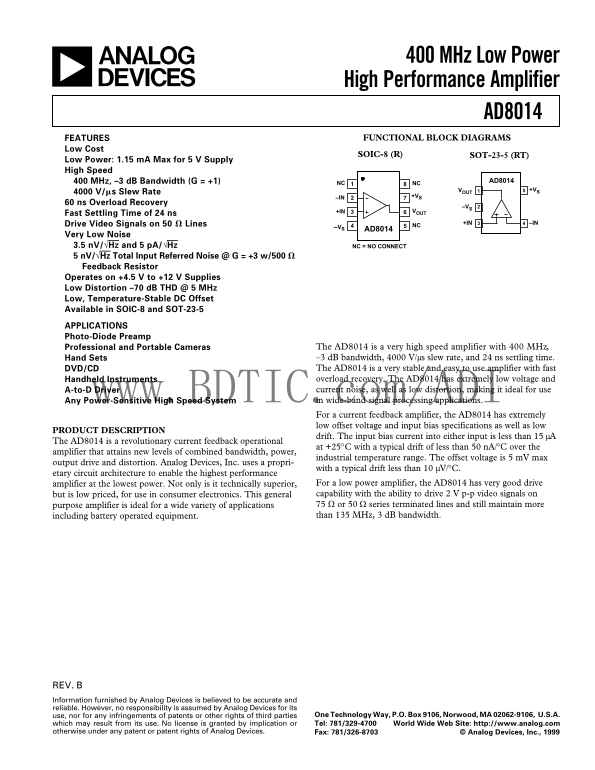
Page 1 Text Content
400 MHz Low Power High Performance Amplifier AD8014 FUNCTIONAL BLOCK DIAGRAMSFEATURES
Low Cost
SOIC-8 (R) SOT-23-5 (RT)
Low Power: 1.15 m A Max for 5 V Supply High Speed
400 MHz, –3 d B Bandwidth (G = +1) AD8014
NC NC
1VOUT +VS
4000 V/ms Slew Rate
–IN +VS
60 ns Overload Recovery
+IN VOUT
Fast Settling Time of 24 ns
Drive Video Signals on 50 V Lines +IN –IN
–VS 5AD8014 NC
Very Low Noise 3.5 n V/√Hz and 5 p A/√Hz NC = NO CONNECT 5 n V/√Hz Total Input Referred Noise @ G = +3 w/500 V Feedback Resistor Operates on +4.5 V to +12 V Supplies Low Distortion –70 d B THD @ 5 MHz Low, Temperature-Stable DC Offset Available in SOIC-8 and SOT-23-5
APPLICATIONS Photo-Diode Preamp
Professional and Portable Cameras The AD8014 is a very high speed amplifier with 400 MHz, Hand Sets –3 d B bandwidth, 4000 V/µs slew rate, and 24 ns settling time. DVD/CD The AD8014 is a very stable and easy to use amplifier with fast Handheld Instruments overload recovery. The AD8014 has extremely low voltage and A-to-D Driver current noise, as well as low distortion, making it ideal for use Any Power-Sensitive High Speed System ww.BDTIC.com/ADI in wide-band signal processing applications. For a current feedback amplifier, the AD8014 has extremely low offset voltage and input bias specifications as well as low
PRODUCT DESCRIPTION
drift. The input bias current into either input is less than 15 µA
The AD8014 is a revolutionary current feedback operational
at +25°C with a typical drift of less than 50 n A/°C over the
amplifier that attains new levels of combined bandwidth, power,
industrial temperature range. The offset voltage is 5 m V max
output drive and distortion. Analog Devices, Inc. uses a propri-
with a typical drift less than 10 µV/°C.
etary circuit architecture to enable the highest performance
amplifier at the lowest power. Not only is it technically superior, For a low power amplifier, the AD8014 has very good drive but is low priced, for use in consumer electronics. This general capability with the ability to drive 2 V p-p video signals on purpose amplifier is ideal for a wide variety of applications 75 Ω or 50 Ω series terminated lines and still maintain more including battery operated equipment. than 135 MHz, 3 d B bandwidth.
REV. Information furnished by Analog Devices is believed to be accurate and reliable. However, no responsibility is assumed by Analog Devices for its
use, nor for any infringements of patents or other rights of third parties One Technology Way, P.O. Box 9106, Norwood, MA 02062-9106, U.S.A. which may result from its use. No license is granted by implication or Tel: 781/329-4700 World Wide Web Site: http://www.analog.com
otherwise under any patent or patent rights of Analog Devices. Fax: 781/326-8703 © Analog Devices, Inc., 1999
Page Summary Contents For AD8014 Analog Devices Data Sheet/Manual
Manual Details
| Brand | Analog Devices |
|---|---|
| Pages | 10 |
| File Size | 153.86 KB |
| Published | June 15, 2026 |
Enter the captcha to get the download link:
